

 English
 中文简体
中文简体 Español
 عربى
عربىIndustry News
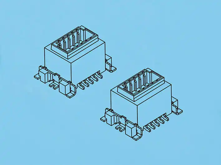
Home / News / Industry News / Signal Attenuation Characteristics of Board to Board Power Connectors Across Frequency Bands
In the realm of electronic engineering, the performance of Board to Board Power Connectors is a critical aspect that determines the efficiency and reliability of signal transmission. As the frequency of the signals being transmitted increases, the behavior of these connectors can change, causing varying degrees of signal attenuation. Understanding the signal decay in Board to Board Power Connectors at different frequencies is essential for designing robust electronic systems that can maintain signal integrity over a wide range of operational conditions. This article will explore the signal attenuation characteristics of Board to Board Power Connectors in various frequency scenarios, providing insights into their performance and potential limitations.
The signal attenuation in Board to Board Power Connectors is influenced by several factors, including the materials used in their construction, the design of the connectors, and the length of the connection. At lower frequencies, the signal loss through Board to Board Power Connectors is typical, allowing for clear and stable transmission. However, as the frequency increases, the resistance and inductance within the connectors can cause increased signal attenuation.
To mitigate this, manufacturers of Board to Board Power Connectors often use high-quality materials that exhibit low resistivity and low inductance. Gold-plated contacts, for instance, are a common choice due to their good conductivity and resistance to corrosion, which helps maintain signal integrity even at higher frequencies. Additionally, the design of the connectors can include features such as shielding and impedance matching to reduce signal loss and ensure that the transmitted signals remain strong and clear.
When analyzing the signal attenuation of Board to Board Power Connectors, it is also important to consider the frequency-dependent behavior of the dielectric materials used in their insulators. Dielectric materials can exhibit different properties at different frequencies, which can affect the transmission of signals through the connectors. High-frequency signals may experience greater attenuation due to the increased dielectric losses in the insulating material.
Another aspect to consider is the length of the connection between the boards. Longer connections can cause higher signal attenuation due to the increased resistance and inductance along the path of the signal. Therefore, in high-frequency applications, it is often advisable to use shorter Board to Board Power Connectors to decrease signal loss.
In high-speed data transmission applications, the signal integrity of Board to Board Power Connectors is important. High-frequency signals, such as those used in gigabit Ethernet or high-definition video transmission, can be particularly susceptible to attenuation. To address this, some Board to Board Power Connectors are designed with specific features, such as differential signaling, to maintain signal integrity over longer distances and at higher frequencies.
Testing and simulation tools are also crucial in understanding the signal attenuation characteristics of Board to Board Power Connectors. Engineers can use these tools to model the behavior of the connectors at different frequencies and under various conditions, allowing them to predict and mitigate potential signal loss issues before the connectors are put into production.
In conclusion, the signal attenuation of Board to Board Power Connectors is a complex phenomenon that depends on multiple factors, including frequency, material properties, connector design, and connection length. By understanding these factors and utilizing advanced materials and design features, manufacturers can produce Board to Board Power Connectors that maintain signal integrity across a broad spectrum of frequencies. This ensures that electronic devices can operate reliably and efficiently, even in demanding high-frequency applications.


")
")


Copyright © Zhejiang Wenda Electronics Co., Ltd. All Rights Reserved

Custom Electronic Connectors Manufacturer

