


 English
 中文简体
 Español
 عربى
Industry News
Home / News / Industry News / How Do Different Card Edge Connector Types and Contact Plating Materials Affect Reliability?
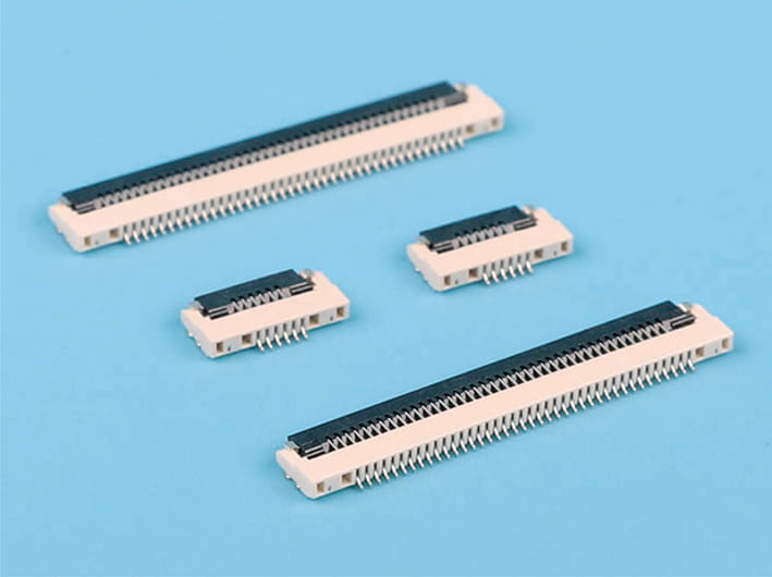
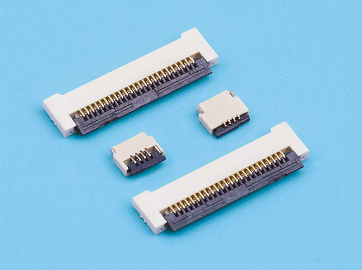
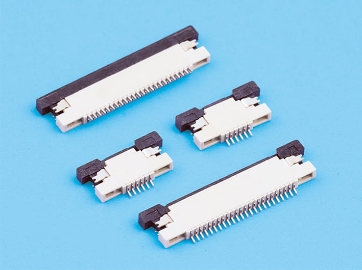
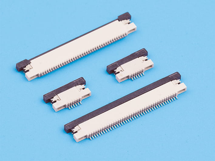
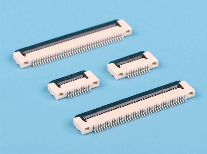
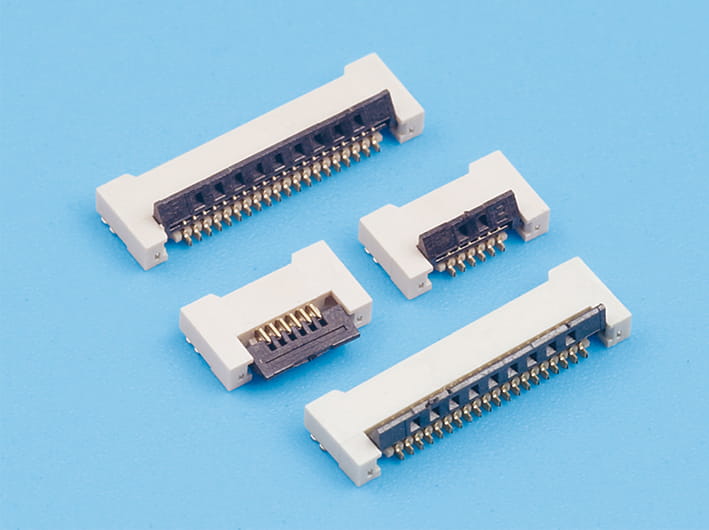
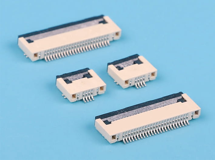
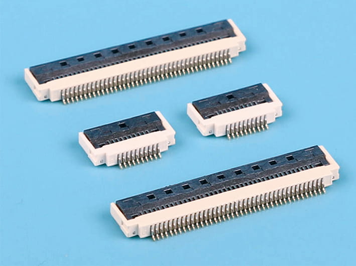
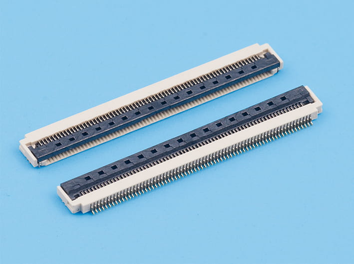
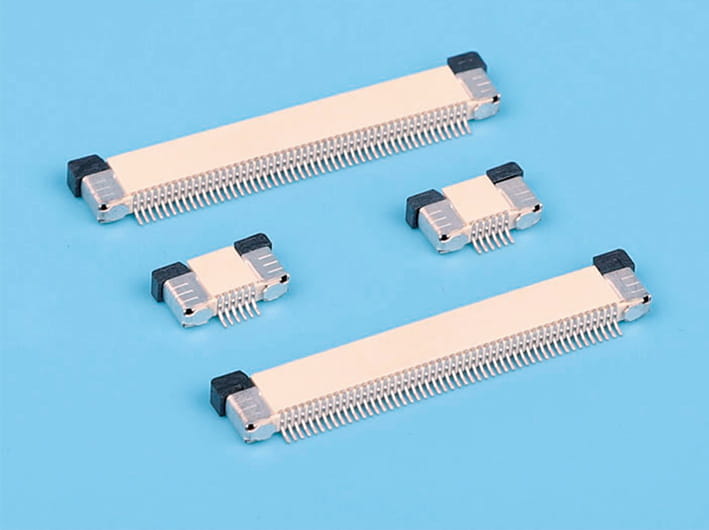
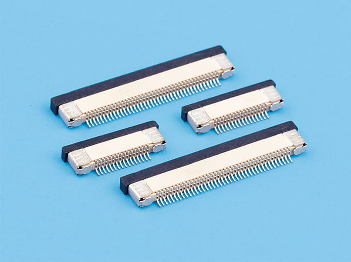
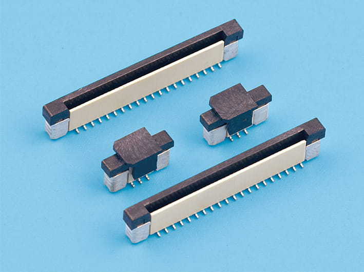
Card edge connectors show up in computers, industrial control systems, communication gear, automotive electronics, embedded devices. They link exposed conductive pads on a PCB to spring contacts inside a mating connector. Compact interface, easy to install and replace. But reliability isn't just about dimensions. Different connector types fit different electrical and mechanical jobs. Contact plating affects corrosion resistance, contact resistance, and wear during repeated insertion. Pick the right combination and you cut intermittent connections, signal degradation, and early failure.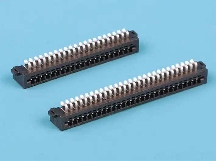
What Are the Main Card Edge Connector Types?
Card edge connectors vary by contact arrangement, pitch, mechanical structure, and intended use. Each design has to match the PCB edge, operating environment, and electrical needs of the equipment.
|
Connector type |
Typical application |
Key reliability consideration |
|---|---|---|
|
Standard card edge connector |
Industrial control boards and expansion cards |
PCB thickness, alignment, and contact retention |
|
High-density card edge connector |
Compact electronic assemblies |
Fine contact pitch, manufacturing tolerance, and signal integrity |
|
PCIe card edge connector |
Desktop computers, servers, and expansion hardware |
Contact geometry, insertion alignment, and high-speed signal performance |
|
Memory card edge connector |
DIMM and other memory-module interfaces |
Contact wear, retention force, and repeated insertion |
|
Power-oriented card edge connector |
Power distribution and high-current circuit boards |
Contact resistance, temperature rise, and current rating |
These categories can overlap. A high-density connector might also handle high-speed signals. The right choice depends on the full interface spec: contact count, pitch, PCB thickness, current needs, expected mating cycles.
How Connector Design Influences Mechanical Reliability
Mechanical design decides how consistently contacts engage with the PCB pads. Contact geometry and spring force are big. Contacts need enough normal force to keep electrical continuity despite vibration, minor dimensional variation, and movement during operation. Too little force means higher contact resistance or intermittent connections. Too much force speeds up wear on contact surfaces and PCB pads.
Alignment matters too. If the PCB enters at a wrong angle or doesn't seat fully, contacts can get uneven loading or damage. Polarization features, retention clips, guide structures, proper insertion geometry help reduce these risks.
For high-speed applications, contact layout and electrical geometry become extra concerns. Impedance discontinuities, crosstalk, return-path limits can hurt signal quality even when the physical connection seems stable. So connector selection should look at both mechanical durability and electrical performance.
Why Contact Plating Materials Matter for Reliability
The conductive surface of a card edge connection has to maintain a stable, low-resistance interface over its service life. Plating helps control corrosion, wear, and electrical degradation. Gold and tin are common, but they behave differently.
Gold plating resists oxidation and corrosion. It's often picked for signal contacts, especially where low contact resistance and repeated mating matter. Hard gold alloys are common for applications with significant insertion-cycle requirements because they usually wear better than thin decorative gold finishes.
Tin plating can be a cost-effective choice for some connector systems. But tin surfaces oxidize more easily and can suffer fretting corrosion under vibration or small repeated movements. Tin-plated interfaces also need proper contact design and compatible mating surfaces. The choice should reflect electrical, mechanical, environmental, and cost requirements.
Comparing Gold and Tin Contact Plating
|
Characteristic |
Gold plating |
Tin plating |
|---|---|---|
|
Corrosion resistance |
Generally excellent |
More susceptible to oxidation |
|
Contact resistance stability |
Typically well suited to low-level signals |
Depends more heavily on surface condition and contact design |
|
Repeated mating |
Hard gold can perform well under frequent cycling |
Wear and surface degradation require careful evaluation |
|
Vibration exposure |
Often suitable with appropriate contact force and design |
Fretting corrosion may be a concern |
|
Relative material cost |
Generally higher |
Generally lower |
|
Common selection priorities |
Signal reliability and durability |
Cost-sensitive applications with compatible interface requirements |
Plating thickness, alloy composition, substrate preparation, and manufacturing quality all affect performance. A connector described simply as "gold plated" may have a thin gold flash or a thicker hard-gold finish. These aren't equivalent in wear resistance. Check the manufacturer's plating specs, including contact area covered, plating thickness, and any underplating. Nickel is commonly applied beneath gold as a barrier layer.
How Insertion Cycles and Environmental Conditions Affect Contact Life
Every insertion and removal cycle causes mechanical interaction between connector contacts and PCB pads. Over time, friction wears the plating, exposes underlying materials, and changes the contact interface. The expected mating-cycle rating should match the product's actual service requirements. A connector used for permanent installation may have very different needs from one used for frequently replaced expansion cards or serviceable industrial modules.
Environmental conditions also influence reliability. High humidity and corrosive contaminants can accelerate degradation. Temperature changes can affect dimensional fit and material behavior. Vibration may cause microscopic movement between contacts, increasing fretting-related resistance changes. For harsh environments, evaluate the complete assembly: PCB finish, connector housing, contact design, retention mechanism, and protection from contaminants. Contact plating alone cannot eliminate every failure mechanism.
Which Tests Help Verify Card Edge Connector Reliability?
Manufacturers and design engineers should select verification tests according to intended use and applicable product requirements.
Important tests include:
Test methods and acceptance limits should be documented before evaluation. For high-speed interfaces, additional signal-integrity measurements may be necessary because acceptable DC contact resistance doesn't automatically guarantee reliable high-frequency performance.
How to Select the Right Connector and Plating Combination
Start by defining operating requirements: signal frequency, current, expected mating cycles, vibration exposure, ambient conditions, maintenance frequency. Then confirm the connector's dimensions and contact arrangement match the PCB design.
For frequently serviced signal interfaces, a properly specified hard-gold contact system may offer a sensible balance of wear resistance and corrosion protection. For cost-sensitive applications with compatible contact designs and limited environmental demands, tin may be suitable.
Request documented specifications for contact plating, mating-cycle ratings, electrical characteristics, and relevant qualification tests. Where reliability is critical, validate the assembled PCB and connector under realistic operating conditions.
A dependable card edge connection results from coordinated engineering of contact geometry, plating material, PCB finish, and environmental protection. Evaluating these factors together helps equipment designers achieve stable electrical performance and reduce maintenance risks throughout the product's service life.


Copyright © Zhejiang Wenda Electronics Co., Ltd. All Rights Reserved

Custom Electronic Connectors Manufacturer

