


 English
 中文简体
中文简体 Español
 عربى
عربىIndustry News
Home / News / Industry News / What Testing Should Manufacturers Perform on Custom Electronic Connectors Before Shipment?
Custom electronic connectors have to fit the devices they're built for and keep working once they're installed. A quick look over, though, won't catch every flaw. A loose contact, a weak crimp, or a nicked insulator can sit there unnoticed until the connector drops a signal, runs hot, or takes a piece of equipment down.
Before an order goes out, manufacturers need to confirm the connectors actually match the approved drawings and what the customer signed off on. The exact test lineup shifts with the application, but electrical performance, mechanical strength, dimensions, and workmanship all deserve a look.
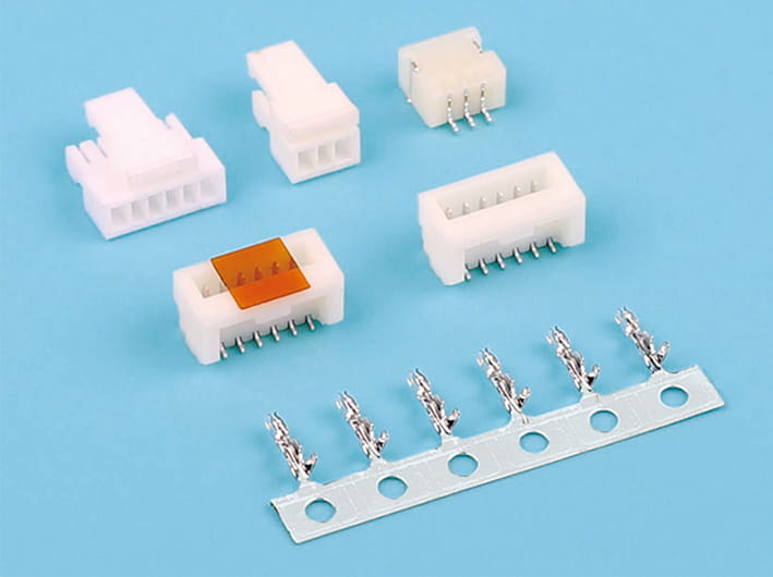
A continuity test checks that each circuit is closed and that the pins land where they're supposed to. It turns up missing contacts, broken runs, and wiring mix-ups. When you're dealing with connectors that have a lot of pins, automated fixtures pay for themselves.
Continuity by itself isn't enough, though. A circuit can be closed and still carry way too much contact resistance. That shows up as voltage drops, stray heat, or jittery signals. For really low resistance numbers, a four-wire Kelvin setup helps cancel out the resistance sitting in the test leads.
Set clear acceptance limits, and use fixtures that land consistently on the test points the spec calls out.
Separate circuits need to stay electrically separate. Insulation resistance testing looks at whether the insulating material is actually stopping unwanted leakage. Low readings can point to moisture, grime, damaged insulation, or contacts that are just too close together.
Dielectric withstand testing—hipot, for short—drops a specified voltage across conductive parts to see whether the insulation survives the electrical stress without breaking down. The two tests do different jobs; don't treat one as a stand-in for the other.
Run the voltage and duration the product calls for. Push too hard and you can damage the connector or the electronics sitting next to it. Jot the results down, and dig into any failures before you sign off on the batch.
Connectors have to stay put through assembly and daily use. Insertion and withdrawal tests measure the force it takes to push the mates together and pull them apart. Weird numbers here can mean misalignment, wrong dimensions, or damaged contacts.
Terminal-retention tests check whether the contacts are really seated in the housing. With cable assemblies, a pull test confirms the wire terminations can take the force they're rated for. Locking tabs should click into place and not let go by accident.
Reusable connectors may need mating-cycle testing. After repeated plugging and unplugging, give the housing, latch, contact plating, and electrical resistance a look for wear. Cable assemblies also need a close eye on crimps and strain relief.
A connector can pass every electrical test and still fail on the assembly line because the dimensions are off. Hold the real product up against the latest approved drawing. Check the things that matter—pin spacing, contact positions, housing size, mounting holes, mating surfaces.
Calipers and micrometers cover a lot of routine measuring. Tighter tolerances might call for optical systems, pin gauges, or a coordinate measuring machine.
Visual inspection catches things numbers miss. Keep an eye out for bent contacts, cracked housings, burrs, damaged threads, scratched plating, corrosion, and wrong markings. With cable assemblies, look at crimp quality, exposed conductors, insulation support, and how the wires sit. Written inspection criteria help different inspectors land on the same call.
A connector living indoors sees a world away from one bolted into a vehicle or left out in the weather. The environmental tests should line up with what the product will actually face in service.
| Test | What it checks | Possible application |
|---|---|---|
| Thermal cycling | Resistance to repeated temperature swings | Automotive and industrial gear |
| High- or low-temperature exposure | Material stability and operation at the limits | Outdoor electronics |
| Humidity testing | Moisture-driven insulation issues and corrosion | Humid environments |
| Vibration and shock | Loosening, damage, intermittent contact | Vehicles and machinery |
| Salt-spray testing | Corrosion resistance under set conditions | Marine or coastal equipment |
| Ingress protection testing | Resistance to dust or water | Sealed outdoor connectors |
Not every product needs every test. The choice comes down to customer requirements, the operating environment, risk, and the relevant standards. After exposure, inspect the connector and rerun electrical tests where that makes sense. A shift in resistance or insulation performance can reveal damage you couldn't see going in.
A connector can sail through continuity and still mangle the signal. That shows up fast in high-speed data and RF work, where impedance shifts and cross-talk between contacts can distort what's passing through.
Depending on the design, testing might cover characteristic impedance, insertion loss, return loss, and crosstalk. A vector network analyzer is the usual tool for RF and high-speed measurements.
Results depend on the fixture, the calibration, and the frequency range. Set acceptance limits against the interface spec. High-speed data connectors may need detailed frequency-based testing, while low-speed control connectors can get by with less.
Power connectors have to carry their rated current without cooking past the allowed temperature. Current and temperature-rise testing shows how much heat builds up under defined operating conditions.
What you see depends on contact resistance, wire size, mounting, ambient temperature, and how many circuits are live. Test the connector in its intended configuration, and record the current, ambient temperature, measurement points, and the temperature rise once the readings settle.
Use the acceptance limits from the approved design and any applicable requirements. Compact connectors deserve extra attention—there's less room for heat to escape. The test evidence should back up the current rating you're printing on the datasheet.
The quality plan should spell out which tests run on every unit and which can be sampled. Qualification and periodic tests need defining too. How you sample should reflect product risk, customer agreements, and whatever regulations apply.
Before shipment, go over the results and chase down any failures. Note the corrective actions and keep traceable records—part number, drawing revision, production lot, materials. The measuring gear has to be calibrated or verified as required.
Final inspection covers quantities, labels, protective caps, packaging, and shipping paperwork. The packaging has to shield contacts from impact and contamination. Moisture protection or ESD safeguards may be in the mix as well.
On the standards side, IEC 60512 and the EIA-364 series cover connector test methods. IPC/WHMA-A-620 may apply to cable and wire-harness workmanship. Confirm the applicable standard, edition, test method, and acceptance criteria for the product.
A practical pre-shipment plan pulls together electrical, mechanical, dimensional, and application-specific testing. When the checks line up with how the connector will actually run, manufacturers can catch defects before delivery, cut down on avoidable returns, and stand behind the fact that the products meet what was agreed on.


Copyright © Zhejiang Wenda Electronics Co., Ltd. All Rights Reserved

Custom Electronic Connectors Manufacturer

