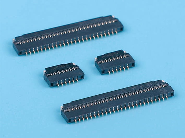
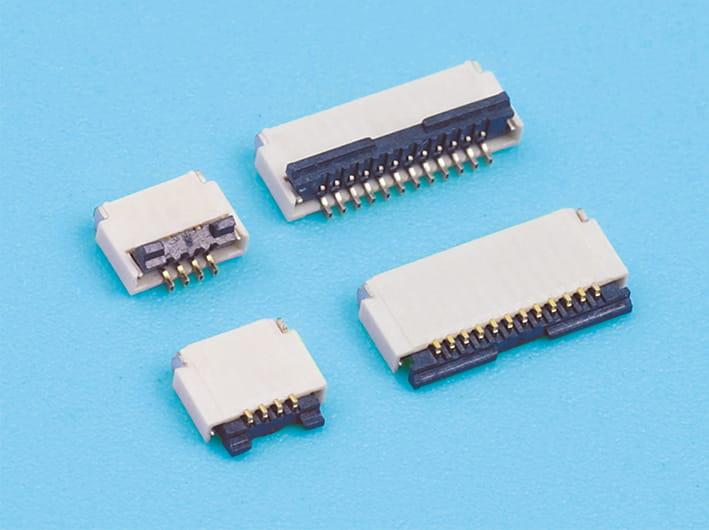
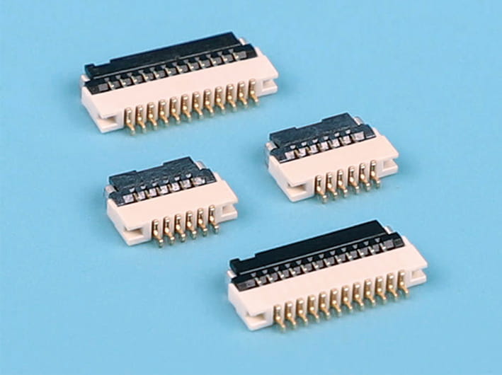
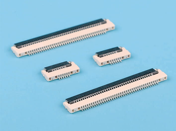
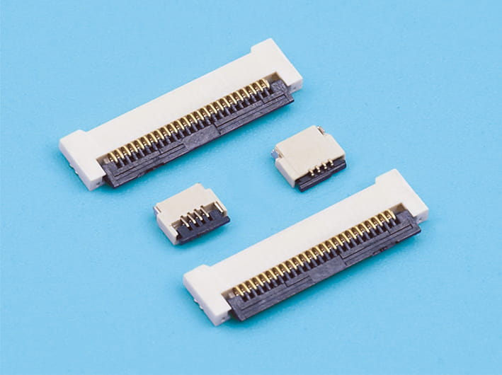
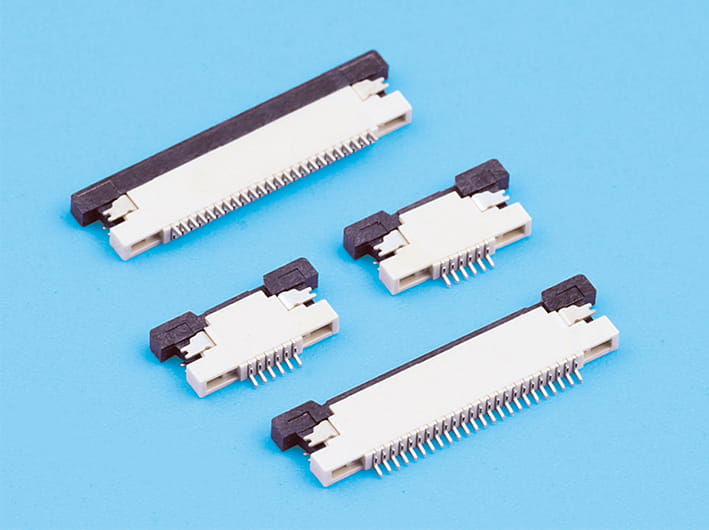
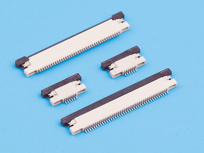
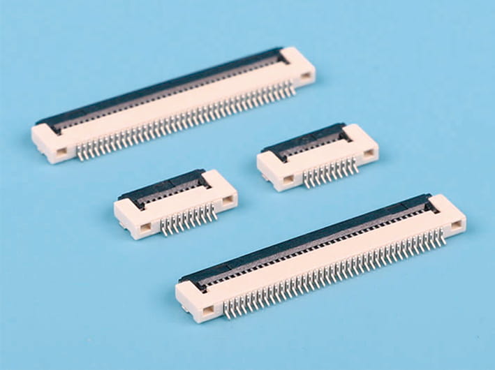
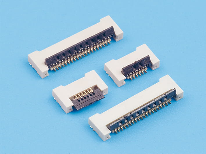
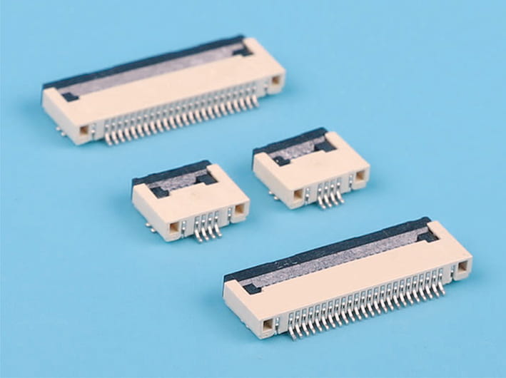
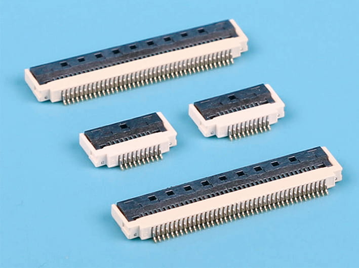
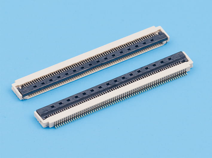
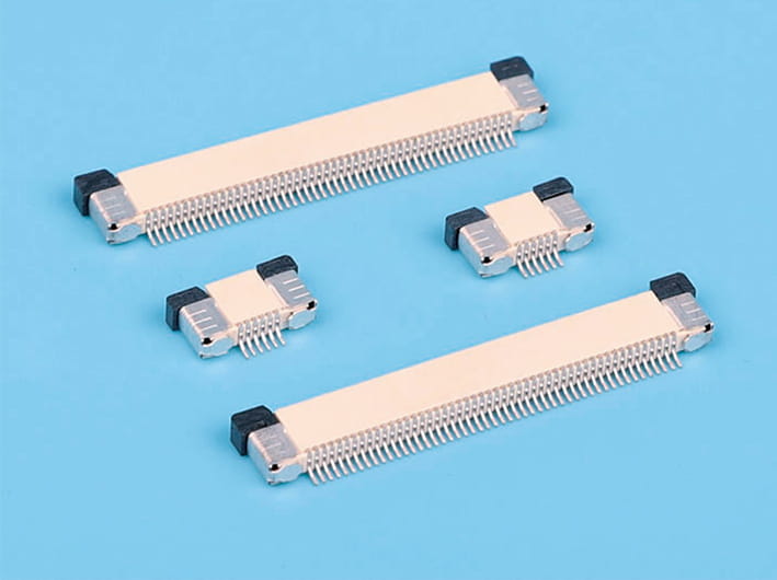
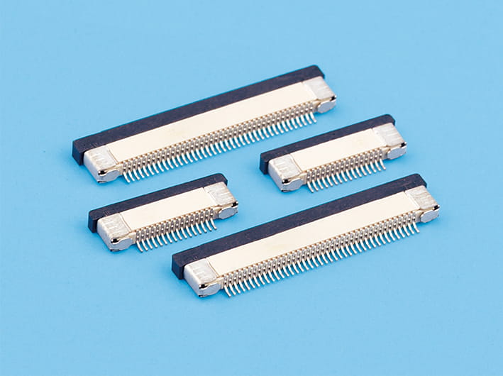
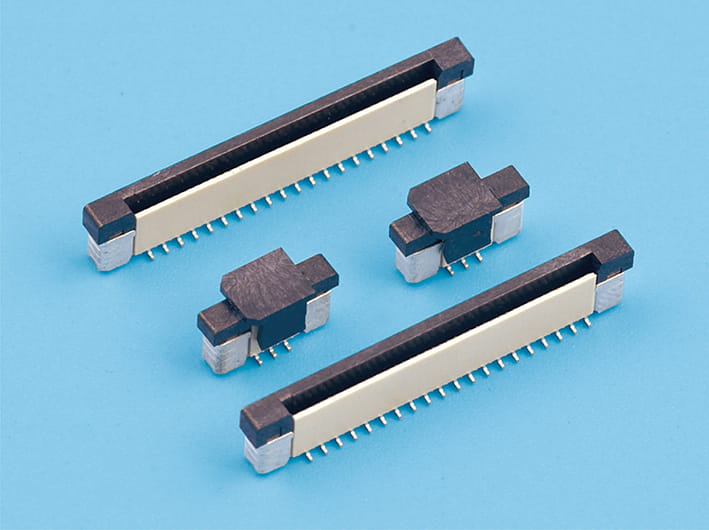
Board-to-board connectors are used when two PCBs need to connect directly inside the same product. You’ll find them in industrial controls, telecom equipment, consumer electronics, automotive modules, medical devices, power equipment, and plenty of other compact electronic products.
When engineers choose a board-to-board connector, pitch is usually one of the first dimensions they check. But Board-To-Board Connector Spacing is about more than just the distance between two contacts. Pitch can affect PCB routing, connector width, mechanical alignment, signal performance, assembly tolerance, and how much useful space is left on the board.
For manufacturers, distributors, and OEM buyers, understanding this relationship early can prevent layout changes and production problems later. Nobody wants to redesign a PCB after the connector tooling and board layout are already finished.
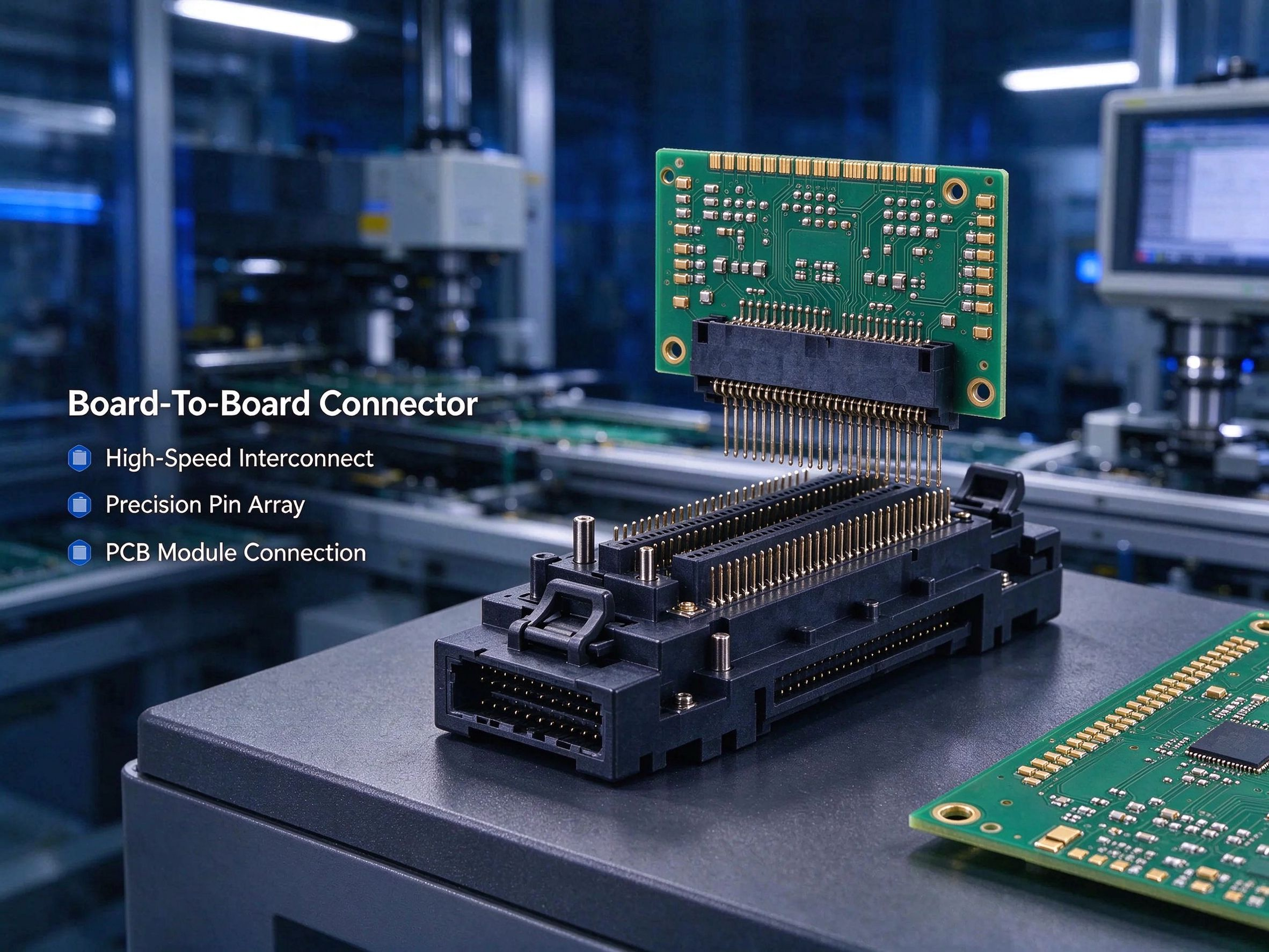
What Does Pitch Mean in a Board-to-Board Connector?
In connector terminology, pitch normally means the center-to-center distance between two neighboring contacts.
For example, a connector with a 0.5 mm pitch has 0.5 mm between the centerlines of adjacent contacts. With a 1.0 mm pitch, the contacts sit farther apart.
This distance determines how closely the contacts can be packed together. Smaller pitch generally allows more contacts to fit into a limited connector width, while larger pitch leaves more physical room around each contact.
There is one detail worth keeping in mind: contact pitch is not the same thing as every clearance on the PCB. It doesn't directly tell you the spacing between solder pads, conductive traces, housing walls, or nearby components. Those dimensions depend on the connector construction and the recommended PCB footprint.
How Connector Pitch Changes Available PCB Space
One of the easiest effects of pitch to see is the amount of board space needed by the connector.
Imagine an application that needs 40 contacts. With a fine-pitch connector, those contacts can fit into a fairly narrow row. Move to a larger pitch and the same 40 contacts will take up more width.
| Typical pitch |
General PCB impact |
Common design consideration |
| 0.4 mm |
Very compact |
Fine-pitch routing and tight manufacturing tolerances |
| 0.5 mm |
Compact |
Careful footprint and assembly control |
| 0.8 mm |
Moderate spacing |
Easier PCB routing than finer pitches |
| 1.0 mm |
More physical room |
Useful where space is less restricted |
| 1.27 mm and above |
Wider layout |
Simpler handling and routing in many designs |
These are general examples, not fixed rules for every connector. Actual contact density, stack height, current rating, and housing dimensions can vary considerably between connector series.
In a compact electronic product, a smaller pitch can free up valuable PCB space. That extra area might be used for components, mounting holes, thermal structures, or routing. But there is a trade-off. Push the pitch too small and PCB fabrication, assembly, and inspection can become more demanding.
Why Smaller Pitch Can Make PCB Routing More Difficult
A fine-pitch connector is attractive when board space is tight, but getting all those signals away from the connector can be another story.
With a larger pitch, there is generally more room to route traces out from the pads. As the pitch gets smaller, trace width, trace spacing, via size, and via-to-pad clearance become much more important.
This is especially noticeable when the connector carries a large number of signals across a multilayer PCB.
Engineers may need to consider:
- Trace width and spacing
- Escape routing strategy
- Via diameter and aspect ratio
- PCB layer count
- Impedance-controlled routing
- Differential-pair requirements
- Manufacturing design rules
So, a connector that saves space on the board can sometimes create extra work somewhere else. The connector itself may not be the expensive part. The PCB fabrication process and additional routing requirements can have a bigger effect on total cost.
Pitch Also Influences High-Speed Signal Performance
For low-speed control circuits, pitch may mainly be a mechanical and layout decision. Once signals become faster, though, the electrical side needs more attention.
When contacts are packed closely together, neighboring signal paths can interact with each other. How much this matters depends on the connector structure and the signals being carried.
Some factors include:
- Signal frequency and edge rate
- Contact geometry
- Dielectric materials
- Shielding
- Grounding arrangement
- Trace routing
- Connector stack height
- Differential-pair structure
A small pitch does not automatically mean poor high-speed performance. There are fine-pitch connectors specifically designed for high-speed applications. The important thing is whether the connector's electrical characteristics fit the system.
For high-speed PCB designs, engineers should check specifications such as impedance, insertion loss, return loss, crosstalk, and current capacity. Pitch by itself doesn't tell the whole story.
How Board-To-Board Connector Spacing Affects Mechanical Tolerance
Pitch also has a mechanical side, and this is easy to overlook during the initial design stage.
Two PCBs are rarely positioned with zero variation. PCB dimensions, connector placement, mounting hardware, housing dimensions, and board stack-up can all have small tolerances.
With a fine-pitch connector, even a small positional error can become significant compared with the contact spacing. That may make mating more sensitive to alignment.
Because of this, the connector should be checked together with:
- PCB dimensional tolerance
- Connector mounting tolerance
- Mating alignment
- Floating or self-alignment features
- Insertion force
- Housing structure
- Expected mating cycles
Some connector families include floating structures or mechanical guides to handle a certain amount of alignment variation. These features can be useful when the position of the two PCBs cannot be controlled extremely tightly.
PCB Footprint Design Must Match the Actual Connector
Choosing the pitch is only the beginning. The PCB footprint still has to match the actual connector.
Two connectors may both use the same pitch while having different:
- Pad dimensions
- Row spacing
- Contact arrangement
- Mounting tabs
- Soldering requirements
- Body width
- Keep-out areas
For production work, engineers should use the manufacturer's actual drawing and recommended PCB layout data whenever possible. Copying the footprint of a similar-looking connector can cause trouble later.
This matters even more with automated SMT assembly. Small differences in pad size or placement can affect solder paste printing, component placement, and solder joint quality.
How Pitch Affects Manufacturing and Assembly
Fine-pitch board-to-board connectors generally require tighter control during PCB assembly.
When contacts are very close together, solder bridging, insufficient solder, contamination, and placement offset can become more noticeable. Inspection can also be harder when part of the solder joint is hidden under the connector body.
For B2B buyers purchasing connectors in volume, it makes sense to talk with the supplier about manufacturing requirements before locking in the design.
Questions worth asking include:
| Buyer question |
Why it matters |
| What PCB pitch is supported? |
Confirms the connector fits the target density |
| What is the recommended footprint? |
Reduces layout and soldering risk |
| What is the allowable alignment tolerance? |
Helps with mechanical assembly |
| What are the current and voltage ratings? |
Prevents electrical mismatch |
| What mating cycles are specified? |
Important for serviceable equipment |
| Is the connector suitable for SMT or through-hole assembly? |
Affects production method |
| What validation or inspection data is available? |
Helps with production quality control |
A connector supplier should be able to provide mechanical drawings, electrical specifications, material information, and relevant application guidance for the selected connector.
Does Smaller Pitch Always Mean a Smaller and Better Design?
Not necessarily.
A smaller pitch can reduce the width of the connector, but that doesn't mean the entire PCB assembly will automatically become smaller. You may still need room for routing, shielding, mounting, thermal management, or other components.
In some products, a slightly larger pitch can actually make the PCB easier to manufacture and inspect.
Take an industrial controller with plenty of available board space. Reducing a connector from 1.0 mm pitch to 0.5 mm might save some connector width, but if the finer pitch makes routing and assembly much harder, the overall benefit may be limited.
The more useful question is usually not, “How small can we make the pitch?” It is, “What pitch gives us the contact density we need without making the PCB unnecessarily difficult to build?”
Pitch Selection Should Consider Current Capacity as Well
Signal contacts and power contacts don't always have the same requirements.
A connector carrying low-current digital signals can often use a dense contact arrangement. Power applications may need larger contacts, wider conductive paths, or dedicated power terminals.
For connectors carrying both power and signal circuits, engineers should check whether the connector family has different contact options for these functions.
Current capacity depends on several things, including contact material, plating, conductor size, temperature rise, and the number of adjacent contacts carrying current. Pitch alone does not determine how much current a connector can handle.
That's why the full electrical specification should be reviewed before a connector is selected.
Stack Height and Pitch Need to Work Together
Board-to-board connectors often determine the distance between two parallel PCBs. Pitch and stack height are both important, but they refer to different physical dimensions.
Pitch describes the spacing between contacts. Stack height describes the distance between the mating boards.
The required stack height may be affected by:
- Component height on either PCB
- Airflow requirements
- Shielding structures
- Enclosure dimensions
- Cable or connector access
- Thermal clearance
- Mechanical supports
A fine-pitch connector can fit the contact-density requirement and still be wrong for the product if its stack height doesn't work with the surrounding components.
A Practical Way to Choose Board-To-Board Connector Pitch
For OEM and contract manufacturing projects, pitch selection doesn't need to be guesswork. Start with the basic physical requirements.
First, work out how many contacts are needed and how much PCB width is available. Then check whether the connector footprint leaves enough room for the intended routing approach.
Next, look at the electrical requirements. Signal speed, voltage, current, impedance, and crosstalk can rule out connector options that seem suitable from a mechanical standpoint.
Manufacturing capability comes next. PCB fabrication tolerances, SMT equipment, inspection methods, and production volume all influence whether a fine-pitch design makes practical sense.
Finally, test the actual board-to-board connection with prototypes. Check mating force, alignment, electrical continuity, signal behavior, and assembly repeatability. Some problems simply don't show up clearly in a CAD drawing.
What B2B Buyers Should Check Before Ordering
When buying board-to-board connectors in bulk, pitch should be treated as one item in a much larger specification.
A practical review can cover:
Mechanical: pitch, number of rows, contact count, mating height, board-to-board distance, mounting method, and alignment features.
Electrical: rated voltage, rated current, contact resistance, dielectric performance, and high-speed signal characteristics where needed.
Materials: contact material, plating, insulator material, operating temperature, and environmental requirements.
Production: packaging, SMT compatibility, inspection methods, sample approval, tooling requirements, and production consistency.
This kind of review can prevent a common sourcing problem: the connector fits the original PCB drawing, but something goes wrong once the board enters actual production.
Choosing the Right Pitch for a Reliable PCB Design
Board-To-Board Connector Spacing affects several parts of PCB design at the same time. Smaller pitch can save board space and allow more contacts in a limited area, while larger pitch generally gives the designer more room for routing and mechanical tolerance.
There isn't one pitch that works for every PCB. The practical choice depends on available board space, signal requirements, mechanical alignment, PCB fabrication capability, assembly conditions, and production volume.
For connector manufacturers, accurate drawings, footprint data, electrical specifications, and application support are also important. The connector is only one part of the system. Its pitch needs to make sense with the PCB layout, assembly process, and the finished product.



 English
 中文简体
中文简体 Español
 عربى
عربى