

 English
 中文简体
中文简体 Español
 عربى
عربىDetermining FPC Flat Connector Compatibility with PCBs
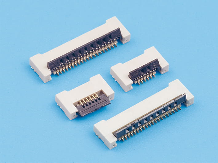
The FPC Flat Connector is a widely used component in electronic assemblies, providing a flexible and reliable connection between flexible printed circuits (FPC) and printed circuit boards (PCB). Ensuring proper compatibility between the connector and the PCB is crucial for performance, signal integrity, and long-term reliability. Understanding the key factors that influence compatibility allows engineers to design robust systems and avoid costly errors.
1. Understanding FPC and PCB Interfaces
- FPC Characteristics: Flexible printed circuits are thin, bendable, and often have fine-pitch conductive traces. Their design varies depending on the application and the amount of current or signal required.
- PCB Features: Printed circuit boards provide a rigid platform with standardized pad layouts and through-hole or surface-mount pads for connector attachment.
- Interface Importance: The interface between an FPC and PCB determines electrical continuity, mechanical stability, and overall reliability of the electronic device.
2. Key Factors for Compatibility
- Pitch Size Matching: The spacing between the FPC connector pins must align precisely with the PCB pads. Even small mismatches can cause short circuits or intermittent connections.
- Connector Type: There are several types of FPC flat connectors, such as ZIF (Zero Insertion Force) and LIF (Low Insertion Force). Each type has specific mechanical requirements for insertion and retention.
- Pad Design: PCB pads should match the connector footprint. Factors such as pad width, length, and plating material impact solderability and electrical contact.
3. Evaluating Electrical Compatibility
- Voltage and Current Ratings: The connector and PCB must handle the required voltage and current without overheating or degradation.
- Signal Integrity: High-frequency signals may require controlled impedance designs. The connector and PCB layout should minimize reflection, crosstalk, and signal loss.
- Contact Resistance: Low contact resistance ensures stable performance, especially for sensitive or high-speed electronic applications.
4. Mechanical Considerations
- Insertion and Retention Force: Ensure that the PCB can accommodate the force required to insert the FPC into the connector without bending or damaging traces.
- Alignment Features: Guide pins, slots, or mechanical stops help maintain proper alignment during assembly.
- Board Flexibility: If the PCB experiences vibration or thermal expansion, the connector must remain seated and maintain electrical contact.
5. Material Compatibility
- Connector Contacts: Typically made of copper alloys with surface plating (gold or tin) to enhance conductivity and prevent corrosion. The PCB pads should be compatible with these materials to avoid oxidation or poor solder joints.
- Thermal Expansion: Both the FPC connector and PCB materials should have similar thermal expansion properties to prevent stress and potential failure under temperature cycling.
- Environmental Considerations: For applications exposed to humidity, dust, or chemicals, choose materials and finishes that maintain reliability over time.
6. Testing and Validation
- Prototype Testing: Before mass production, test the connector-PCB assembly for insertion force, retention, electrical continuity, and signal integrity.
- Mechanical Stress Tests: Simulate vibration, bending, or shock to ensure that the connection remains stable.
- Electrical Performance Tests: Measure resistance, capacitance, and signal quality under operational conditions to validate compatibility.
7. Design Guidelines
- Manufacturer Specifications: Always refer to the connector manufacturer’s datasheet for recommended PCB footprint, pad dimensions, and electrical ratings.
- Clearances: Maintain adequate spacing around the connector for insertion, removal, and assembly tooling.
- Documentation: Create detailed assembly instructions to ensure that technicians or automated assembly lines maintain proper alignment and connection.
8. Maintenance and Long-Term Considerations
- Inspection: Regularly inspect solder joints and connector contacts for signs of wear, corrosion, or misalignment.
- Replacement and Upgrades: If the connector or PCB design changes, re-evaluate compatibility before integration.
- Environmental Protection: Consider conformal coatings or protective housings to extend the life of the connector-PCB assembly.
Ensuring compatibility between an FPC Flat Connector and a PCB requires careful consideration of pitch, connector type, electrical and mechanical properties, material selection, and environmental factors. Proper alignment, testing, and adherence to design guidelines are essential to maintain reliable connections, prevent failures, and achieve suitable performance.
Related Products
-

Easy-on fpc flat ribbon connector, 0.3mm pitch, 1.0mm height, flexible printed circuit connector, horizontal smt type
-

Back flip fpc flat flexible cable connector, 0.3mm pitch, 1.0mm height, bottom contact type for pcb board connections
-

Back flip micro fpc flat cable connector, 0.5mm pitch, 1.0mm height, compact design, white, for data, signal transfer applications
-

0.5mm Pitch, 1.0mm Height, Flip-Type Horizontal FPC Connector
-

0.5mm pitch 1.2mm fpc flat cable connectors, horizontal smt type, flexible printed circuit connectors, secure locking
-

0.5mm Pitch, 1.2mm Height, Rear-Entry Horizontal FPC Connector
-

0.5mm pitch 1.2mm height fpc flat cable connector, zif r/a upper contact, locking slider, high-density integration, durable, for flexible printed circuits
-

0.5mm pitch 1.2mm height fpc flat flexible cable connector, zif r/a down contact, for electronics and pcb boards
-

High-quality 0.5mm pitch 1.5mm height easy-on flat flexible cable fpc connector, horizontal type, locking-style, for pcb circuit board
-
0.5mm pitch 1.5mm height back flip fpc flat connectors, zif slide type, flexible printed circuit cable connectors, horizontal contact
-

0.5mm pitch easy-on fpc flat ribbon connector, 2.0mm height, locking zif slide type, horizontal contact, flexible printed circuit board connector
-

0.5mm pitch 2.0mm height, easy-on r/a with buckle fpc flat connectors, high-density integration flexible printed circuit board connectors
-

0.5mm Pitch, 2.0mm Height, Hinged Cover, Horizontal Mounting, Large Solder Pads
-

0.5mm pitch 2.0mm height back flip fpc flat connectors, horizontal insert, locking type, zif slide, pcb mount
-
")
0.5mm Pitch, Ultra-Thin 2.0mm Horizontal FPC Connector (Pull-Out Locking Type, Top Contact Type)
-
")
0.5mm Pitch, Ultra-Thin 2.0mm Horizontal FPC Connector (Pull-Out Locking Type, Bottom Contact Type)
-

0.5mm pitch 4.5mm height fpc flat cable connector, zif s/t reversed pointer, locking slide
-

Double-side drawing fpc flat connector, 0.5mm pitch, 2.0mm/2.5mm height, flip type, for flexible cable, pcb mountable
CONTACT INFORMATION
-
Mr.Zhou(Sales manager)
Tel:+86(0)577-62369959
Tel:+86(0)577-62378959
MP:+86-13570877599
E-mail:[email protected]
Wechat:+86-13570877599
PRODUCT LINKS

Copyright © Zhejiang Wenda Electronics Co., Ltd. All Rights Reserved

Custom Electronic Connectors Manufacturer
