

 English
 中文简体
中文简体 Español
 عربى
عربىIndustry News
Home / News / Industry News / WTB Connector High Contact Resistance: Causes, Fixes, and How to Avoid It
If you've ever dealt with intermittent signals, overheating connectors, or outright device failures, you might have already run into a hidden culprit: WTB connector high contact resistance. It's one of those problems that doesn't always show up on a basic continuity test but can quietly wreck performance over time.
In this guide, I'll walk you through what actually causes high contact resistance in wire‑to‑board connectors, how to spot it before it causes real trouble, and – importantly – what you can do to fix and prevent it. No fluff, just practical help for engineers, technicians, and buyers who need reliable connections.
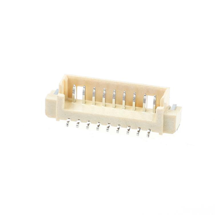
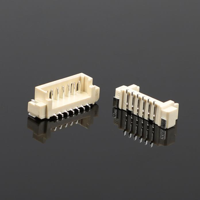
Every WTB (wire‑to‑board) connector is designed to have a very low electrical resistance at the mating interface – typically in the milliohm range. When that resistance climbs above specifications, you get high contact resistance. The immediate effects? Voltage drops, heat buildup, signal distortion, and eventually, melted plastic housings or burned pins.
Think of it like a kink in a garden hose: most of the water (current) still flows, but the kink gets hot, pressure drops, and everything downstream suffers.
From real‑world field failures and lab tests, here are the common reasons:
1. Oxidation or surface contamination – Even a thin film of oxides, sulfides, or manufacturing residue can raise resistance dramatically. This is especially common with tin‑plated terminals in humid or polluted environments.
2. Insufficient normal force – The spring‑like part of the female terminal loses its tension over time (or was under‑designed from the start). Low normal force means fewer microscopic contact points, Finding to higher resistance.
3. Mating misalignment or incomplete insertion – When the wire terminal isn't fully seated into the housing, or the housing latch isn't locked, the contact area is reduced. This is a frequent assembly error.
4. Worn or fretted contacts – Vibration, thermal cycling, or repeated mating cycles can cause fretting corrosion. Tiny wear debris accumulates, forming insulating layers.
5. Wrong wire gauge or damaged crimp – A loose crimp or using a wire that's too thin for the terminal creates a hidden high‑resistance point right inside the insulation.
You don't always need expensive lab gear. Here are practical symptoms:
For a definitive test, use a milliohmmeter (four‑wire Kelvin method). Compare your reading with the connector's datasheet. If it's 20–30% higher than the specified maximum, you're already in the danger zone.
Once you've confirmed the issue, here's what actually works:
Important: If the board‑mount header shows signs of pitting or gold‑worn‑through, replace it too. High resistance often damages both sides.
Choosing the right connector and handling it properly saves endless troubleshooting. Here's what you (as a buyer or designer) can do:
When you're sourcing WTB connectors, don't just compare price per piece. Ask for contact resistance stability data – not just initial values, but after temperature‑humidity aging or vibration tests. Many low‑cost connectors start fine but develop high resistance after a few months in the field.
Also, check if the manufacturer specifies the test method (e.g., EIA‑364‑23). A reliable supplier will provide milliohm readings with a defined test current and open‑circuit voltage. Avoid vague "low resistance" claims.
WTB connector high contact resistance is not a mysterious failure – it's almost always caused by oxidation, low normal force, poor crimping, or fretting. The good news: you can detect it early with a simple voltage drop test, and you can prevent it by choosing the right plating and maintaining proper assembly practices.
Next time you see an intermittent connection or a warm connector, don't just swap the board – check the contact resistance first. A few minutes with a milliohmmeter can save hours of chasing ghosts.
Got a specific WTB connector model or application? Look up its datasheet's "contact resistance" spec and measure yours today. You might be surprised what you find.


")
")


Copyright © Zhejiang Wenda Electronics Co., Ltd. All Rights Reserved

Custom Electronic Connectors Manufacturer

