


 English
 中文简体
 Español
 عربى
Industry News
Home / News / Industry News / How Flexible Flat Ribbon Cable Supports Miniaturization in Modern Electronic Devices
Inside a thin laptop, smartphone or camera, there is very little room for conventional wiring. Several circuit boards, displays, sensors and other components may need to communicate within a tightly packed housing. Bundles of round wires can make routing difficult, particularly when connections must pass through narrow gaps or around moving parts.
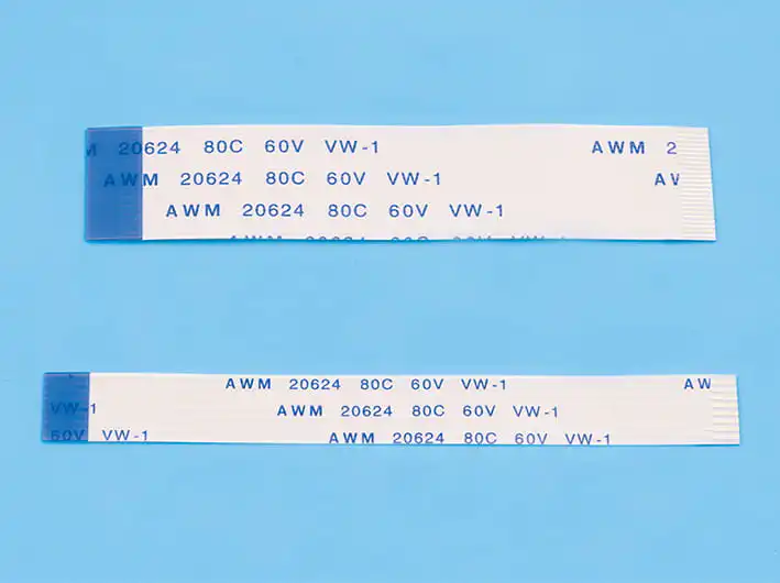
Flexible Flat Ribbon Cable (FFC) offers another way to handle these connections. Its parallel conductors are arranged in a thin, flat structure and separated by insulating film. This allows manufacturers to connect multiple components without using bulky individual wire bundles. For product designers, the main attraction is not simply the cable's small size, but the freedom it gives them when arranging internal components.
Why FFC Takes Up Less Space Than Traditional Wiring
A conventional wire harness contains several individually insulated conductors. These wires need to be bundled, routed and secured, which can consume valuable space inside a compact enclosure.
FFC combines multiple conductors into one flat cable. The conductors are arranged at a defined pitch and laminated between insulating layers, producing a relatively thin connection.
This construction can help engineers:
The actual space savings depend on conductor count, pitch, cable thickness and connector dimensions. A poorly selected connector can take up more room than the cable itself, so both components need to be considered during layout design.
Routing Connections Around Compact Components
Modern electronic products rarely have all their components arranged on one flat surface. A display may connect to a main circuit board, while cameras, sensors and control modules occupy separate positions.
FFC can pass between these components and accommodate bends within its specified limits. This is useful in printers, scanners, display assemblies, cameras and other devices where rigid wiring would complicate the internal layout.
However, repeated bending needs careful attention. A cable designed for a fixed installation may not survive continuous movement in a folding or sliding mechanism.
Engineers should check the minimum bend radius, expected movement cycles and strain around connector ends. Sharp bends, excessive tension and repeated flexing at the same point can eventually damage copper conductors or their insulation.
Fine-Pitch Conductors Allow More Connections in Less Space
FFC products are available with different conductor pitches and counts. A smaller pitch can reduce cable width for a given number of conductors, making it useful in devices where connector space is limited.
The trade-off is tighter manufacturing tolerance. Conductors must remain accurately positioned, and the exposed contact area needs to align with the connector.
| Lubricant type | Potential advantages | Points to consider |
|---|---|---|
| Mineral-oil-based grease | Common industrial option with various formulations | Temperature limits and additive compatibility |
| Synthetic grease | Can offer stable performance across wider temperature conditions | Higher cost and material compatibility |
| Silicone-based lubricant | Useful in selected applications requiring specific material compatibility | Not suitable for every gear contact |
| Gear oil | Suitable for certain enclosed gearbox designs | Viscosity, leakage and sealing requirements |
Before approving a production drawing, confirm the conductor count, pitch, exposed contact length and contact-side orientation. Even a small mismatch can prevent proper connector engagement.
Fewer Individual Wires Can Simplify Assembly
In high-volume electronics manufacturing, every additional wiring operation adds handling time. Connecting several individual wires requires more routing, positioning and termination work than inserting one compatible FFC.
This is particularly useful in assemblies where multiple signals run between two closely positioned components. A single flat cable can replace several separate connections and make the assembly layout easier to reproduce.
Production quality still depends on dimensional accuracy. Manufacturers should pay attention to conductor spacing, insulation bonding, contact plating and cable thickness.
Automated inspection can identify problems such as misaligned conductors, damaged insulation or contamination around contact areas. These checks become increasingly important as connector pitch decreases.
Signal Performance Still Needs Engineering Attention
Making a cable thinner does not automatically make its electrical performance better. In high-density electronic assemblies, closely spaced conductors can create crosstalk, while cable geometry and connector transitions may affect signal transmission.
For ordinary low-speed connections, a standard FFC may be sufficient. Higher-speed applications require more detailed evaluation of conductor dimensions, dielectric properties, grounding arrangements and electromagnetic interference.
Depending on the interface, designers may need additional ground conductors or shielding. Signal integrity can then be checked through measurements such as insertion loss, return loss and crosstalk using the actual cable and connector configuration.
FFC should therefore be selected according to the signal requirements, rather than assuming that every flat cable is suitable for high-speed data transmission.
Insulation and Conductor Materials
Material selection affects flexibility, temperature resistance and electrical insulation.
Polyester film is widely used in general-purpose FFC products because it provides a thin, flexible insulating layer. Polyimide is another option for applications requiring different thermal or mechanical properties, although it may increase material costs.
Copper or copper-based materials are commonly used for conductors. Contact surfaces may receive additional plating to support reliable connections and improve resistance to corrosion.
|
Material or feature |
Main function |
Selection consideration |
|---|---|---|
|
Polyester insulation |
Electrical insulation and flexible construction |
Temperature and mechanical requirements |
|
Polyimide insulation |
Insulation for selected demanding environments |
Cost and application conditions |
|
Copper conductors |
Carry electrical signals and power |
Thickness, resistance and current capacity |
|
Contact plating |
Supports connector contact reliability |
Wear and corrosion resistance |
|
Shielding layer |
Helps control interference |
Grounding requirements and added thickness |
Temperature, humidity, vibration and expected service life should all be considered when choosing the material combination.
Check Cable Performance Before Mass Production
A supplier's product description cannot establish whether an FFC will fit a particular electronic assembly. Product developers should request samples and technical drawings showing cable thickness, conductor pitch, length, contact dimensions and material specifications.
Testing should cover electrical continuity, insulation resistance and dielectric withstand where required. Connector retention and repeated-bending tests are also important when the cable will move during normal operation.
For high-speed devices, evaluate signal performance using the actual connector and circuit-board layout. This can expose problems that may not appear during basic continuity testing.
Designing Smaller Devices Without Compromising Connections
FFC makes it easier to arrange multiple electrical connections in spaces where conventional wire bundles would be difficult to accommodate. Its flat profile is useful in compact consumer electronics, medical instruments and industrial control equipment.
The cable still needs to match the application in conductor pitch, insulation material, connector geometry and bending requirements. Getting these details right during the design stage helps avoid connection problems during assembly and gives manufacturers more freedom to develop smaller electronic products.


Copyright © Zhejiang Wenda Electronics Co., Ltd. All Rights Reserved

Custom Electronic Connectors Manufacturer

