


 English
 中文简体
 Español
 عربى
Industry News
Home / News / Industry News / How Do Different Types of FPC Connectors Support Ultra-Thin Electronic Device Designs?
As phones, wearables, cameras, and portable medical devices get thinner, the space available for internal wiring keeps shrinking. Traditional rigid connections are not always practical, particularly when components sit at different angles or need to move independently. Flexible printed circuits (FPCs) solve part of this problem, but they still need connectors that fit the available space and hold the cable securely.
FPC connectors come in several forms. Some use locking mechanisms, others rely on contact pressure, and their contact positions and insertion directions also vary. These differences matter when designing a compact PCB layout.
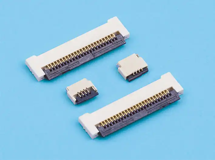
ZIF Connectors: Easier Insertion Without Damaging the FPC
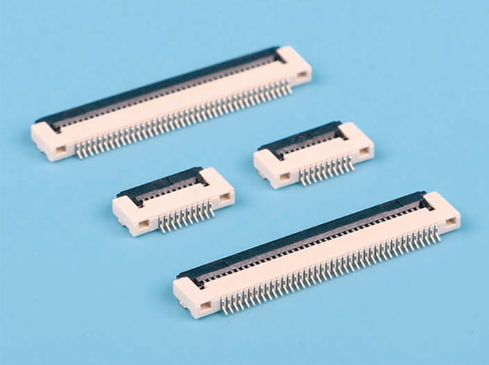
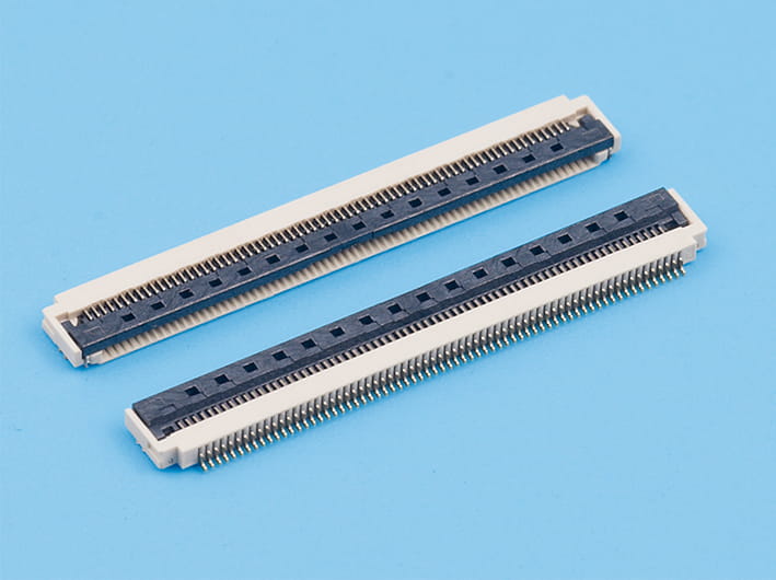
Zero Insertion Force (ZIF) connectors are common in compact electronics because the cable can be inserted without applying significant force to its contacts.
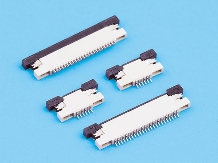
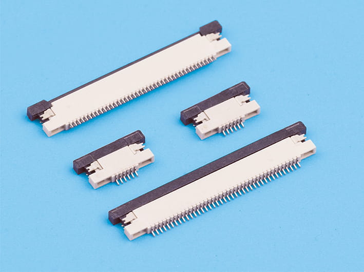
A small lever or sliding lock opens the connector. Once the FPC is in position, the lock closes and presses the exposed conductive pads against the terminals.
This arrangement is useful for display modules, cameras, and other components where delicate flexible circuits need to be connected during assembly. It also makes replacement easier when servicing is required.
The locking mechanism adds some height, however. Designers need to account for actuator clearance, cable thickness, and contact pitch. A cable that is not fully inserted before locking can cause intermittent connections.
Non-ZIF Connectors for Space-Constrained Designs
Non-ZIF connectors use friction and contact pressure to hold the FPC in place. Without a separate locking lever, their construction can be smaller and simpler.
They are often used for connections that are assembled once and rarely disconnected. This can make them suitable for devices where every fraction of internal space matters.
There is a trade-off during assembly. The cable needs to be inserted carefully, since excessive force can damage its conductive pads. Retention force also needs to be sufficient to prevent the FPC from working loose during normal use.
Top-Contact and Bottom-Contact Connectors
The difference between these two designs is where the connector terminals meet the exposed copper pads on the FPC.
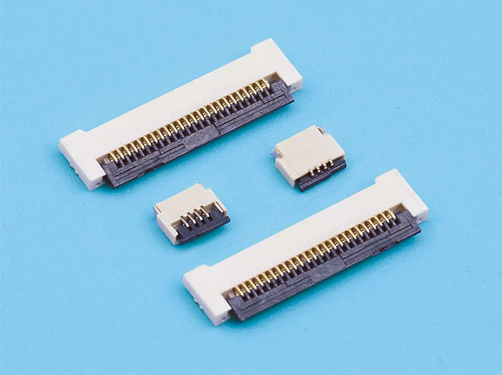
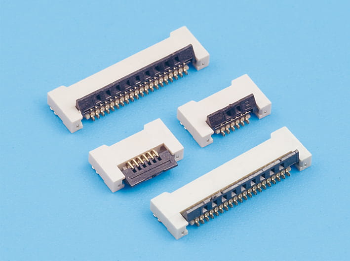
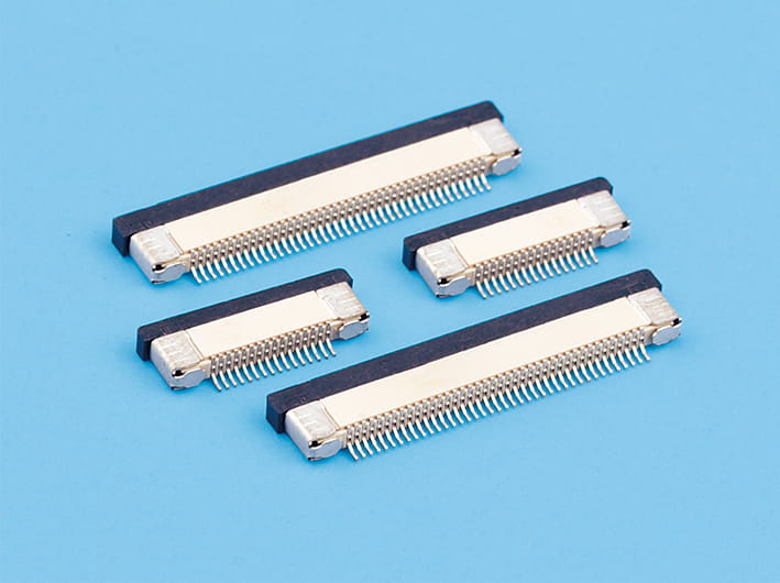
A top-contact connector connects to pads on the upper side of the inserted cable. A bottom-contact version makes contact with the lower side.
This detail may seem minor, but selecting the wrong arrangement can make the FPC impossible to connect correctly without changing the cable design or routing.
Before choosing a connector, check the exposed copper side, insertion direction, terminal layout, and manufacturer's dimensional drawing. Some product families also offer dual-contact designs for specific cable arrangements.
Vertical and Right-Angle FPC Connectors
The direction in which the FPC enters the connector affects PCB layout and available clearance.
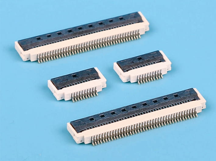
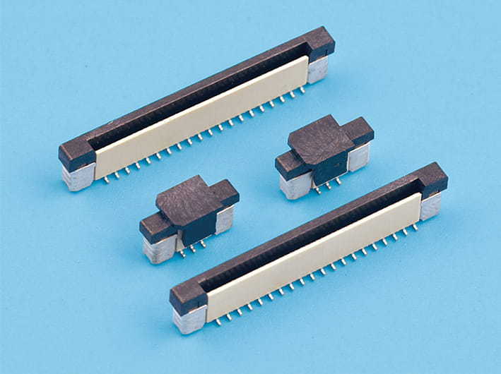
Vertical connectors accept the cable from above. They can work well when the board has enough space above the connector.
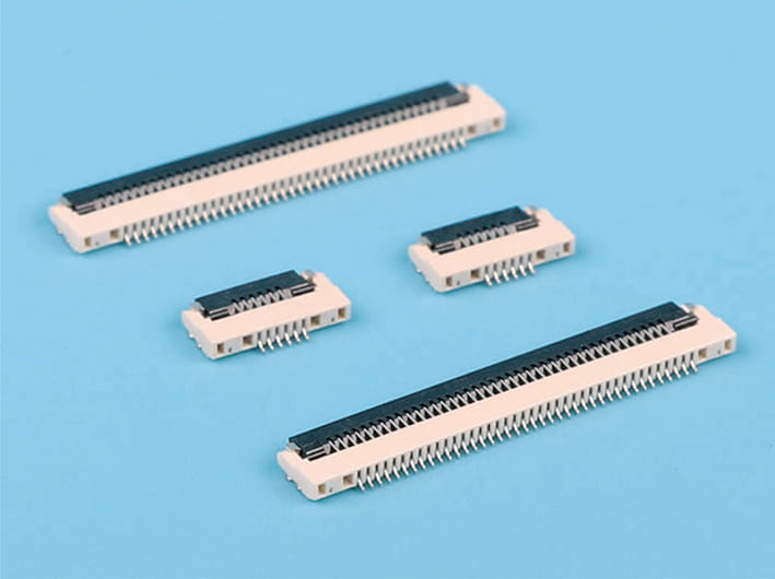
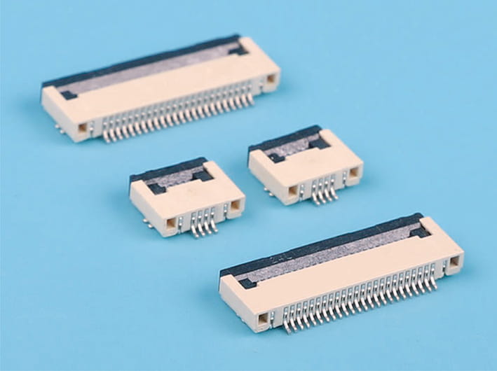
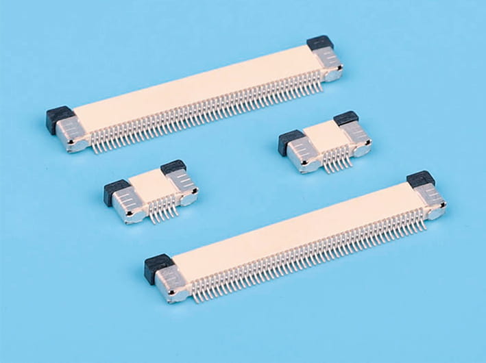
Right-angle connectors guide the cable parallel to the PCB surface. This is often useful in thin devices where there is little vertical clearance or where the FPC needs to run along the board.
| Connector configuration | Main characteristic | Typical application |
|---|---|---|
| ZIF | Locking actuator and low-force insertion | Display and camera connections |
| Non-ZIF | Friction-based cable retention | Compact, permanent connections |
| Top-contact | Connects with pads on the upper FPC surface | Upper-side exposed contacts |
| Bottom-contact | Connects with pads on the lower FPC surface | Lower-side exposed contacts |
| Vertical | Cable enters from above | Boards with sufficient vertical clearance |
| Right-angle | Cable enters parallel to the PCB | Thin devices with limited height |
These are different design features rather than mutually exclusive connector categories. For example, a connector can be both ZIF and right-angle, with bottom contacts.
Keeping the Overall Device Thin
A low-profile connector can save valuable space, but its actual installed height is only part of the calculation. Engineers also need to allow room for the FPC, locking actuator, solder joints, and cable routing.
The bend radius deserves particular attention. Folding a flexible circuit too sharply near its connector can damage copper traces or create stress around the contact area. Repeated movement makes this more serious in devices with hinges or moving displays.
Connector placement should therefore be considered alongside the FPC route and surrounding components, rather than added after the PCB layout is complete.
Electrical and Mechanical Specifications to Check
Small connectors still have to carry signals reliably. Reducing their size does not remove the need for adequate contact pressure, current capacity, and mechanical retention.
Several specifications deserve attention:
For high-speed signals, contact pitch alone is not enough. Impedance, crosstalk, insertion loss, and grounding also need to be evaluated with the actual FPC layout.
Connector Materials and Manufacturing Quality
Copper alloys are commonly used for connector terminals because they combine electrical conductivity with useful spring properties. Contact surfaces may receive nickel and gold plating to help control corrosion and maintain stable electrical contact.
The housing is generally made from engineering plastic that must retain its dimensions during soldering and normal operation. Heat resistance matters particularly when connectors are installed through automated PCB assembly.
Manufacturing errors can be difficult to spot visually. Misaligned terminals, inconsistent plating, or a poorly fitted actuator may only become apparent during electrical or mechanical testing.
Before approving a component for mass production, check its dimensions, contact resistance, insertion force, cable retention, and compatibility with the intended soldering process.
Choosing FPC Connectors for Ultra-Thin Electronics
A connector that saves space but makes cable installation difficult may create more problems than it solves. ZIF designs offer controlled locking, non-ZIF versions reduce structural complexity, and contact orientation and insertion direction give engineers more options when arranging internal components.
When selecting FPC connectors, start with the PCB clearance, cable thickness, contact layout, and assembly direction. Then check electrical ratings and mechanical test results against the actual application. These details help prevent connection problems after the device moves from prototype development into mass production.


Copyright © Zhejiang Wenda Electronics Co., Ltd. All Rights Reserved

Custom Electronic Connectors Manufacturer

